Core components are sourced through a localized supply chain to support supply continuity and stable system operation. High-precision magnetic sensing technology supports both single-turn and multi-turn absolute encoder configurations. Supports the PROFIBUS-DP interface for fast and reliable data communication in industrial fieldbus systems. Single-turn resolution up to 16 bit and multi-turn resolution up to 14 bit for high-precision position measurement. High shock and vibration resistance with protection ratings up to IP66 ensures reliable operation in harsh industrial environments. Built-in reverse-polarity and short-circuit protection helps protect the encoder against wiring errors.
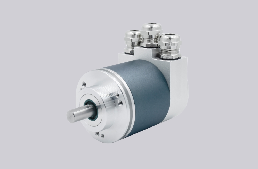
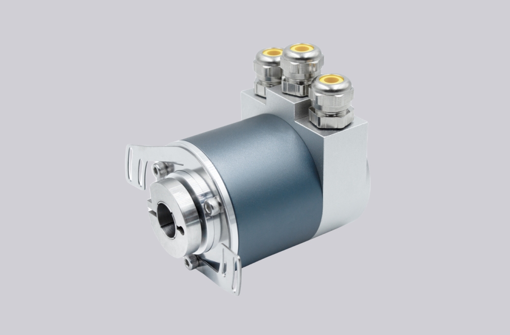
Technical Data
| Product Series | SAS/M58A | SAS/M58C |
|---|---|---|
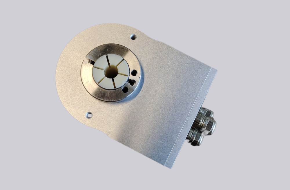
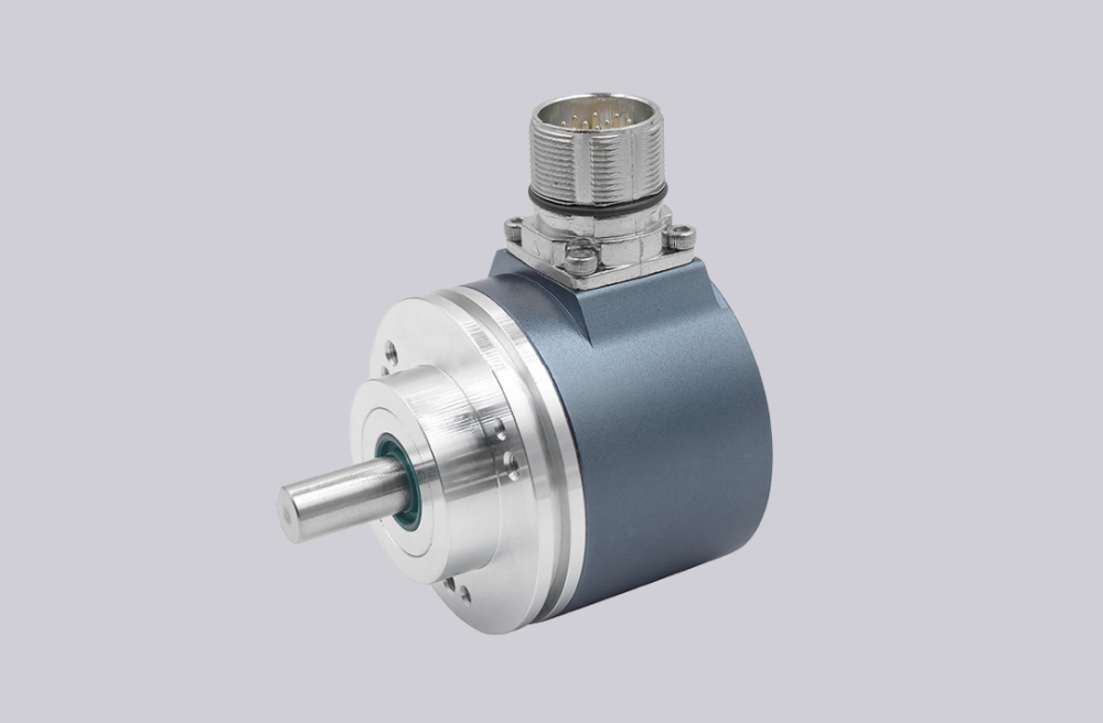
| Shaft Type | Ø58 mm, Solid Shaft | Ø58 mm, Blind Hollow Shaft |
| Shaft Diameter | Ø6, 8, 10, 12, 14, 15 mm (Other shaft diameters available on request) | |
| Housing Material | Aluminum (Stainless steel housing optional) | |
| Communication Interface | PROFIBUS-DP | |
| DP-V0 Functions | MS0, Freeze, Sync, Auto_Baud, Fail_Safe | |
| Output Circuit | RS485-compliant line driver, optically isolated | |
| Function | Single-turn or Multi-turn | |
| Supply Voltage | 10–30 VDC | |
| Single-turn Resolution | 13 bit / 8192; 16 bit / 65536 | |
| Number of Revolutions | 1 revolution (single-turn); 4096 revolutions / 12 bit; up to 16384 revolutions / 14 bit | |
| Power Consumption | ≤1 W | |
| Programmable Functions | Resolution, speed unit, preset (zero position), counting direction, limit switches | |
| Transmission Rate | ≤12 Mbit/s | |
| Manual Settings | Address selector switches 0–99 and termination resistor switch (with terminal box) | |
| Reverse Polarity Protection | Yes | |
| Short-circuit Protection | Yes | |
| Surge and ESD Protection | Yes | |
| Operating Speed | 3000 rpm | |
| Shaft Load | Radial: 200 N; Axial: 100 N | |
| Degree of Protection | IP65 or IP67 | |
| Starting Torque | <0.05 Nm | |
| Operating Temperature | -40°C to +85°C | |
| Storage Temperature | -40°C to +100°C | |
| Shock Resistance | 1000 m/s², 6 ms (100 g) | |
| Vibration Resistance | 20 g | |
| Electrical Connection | 3 × PG9 cable glands; 3 × M12 connectors | |
| Connection Direction | Radial | |
Terminal Assignment
| Signal | Assignment |
|---|---|
| ⊥ | Power supply ground |
| B (Left) | Data line B (input) |
| A (Left) | Data line A (input) |
| (-) | 0 V |
| (+) | 10–30 V |
| B (Right) | Data line B (output) |
| A (Right) | Data line A (output) |
| (-) | 0 V |
| (+) | 10–30 V |
| The power supply only needs to be connected once, regardless of which terminal group is used. When the termination resistor is switched on, the outgoing bus connection is disconnected. |
LED Indicators and Operating Principle
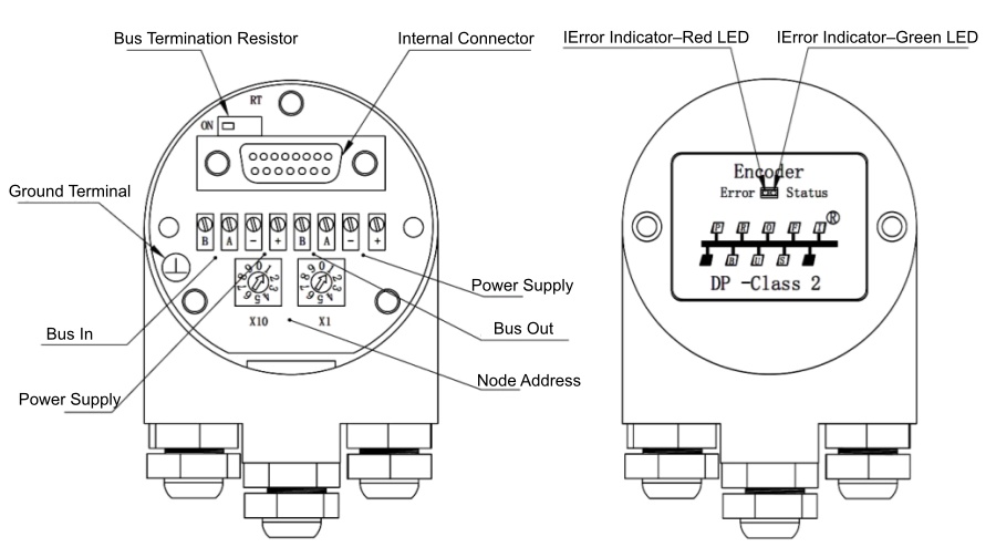
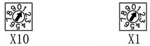
Slave Address Setting:
The slave address can be set using two rotary switches. The address range is 1–99, and each address may only be used once on the bus.
Termination Resistor Setting:
The termination resistor RT can be connected to the bus using the switch.
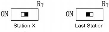
LED Indicators
| Red LED | Green LED | Status Information / Possible Cause |
|---|---|---|
| Off | Off | No power supply |
| On | Flashing |
Encoder is ready for operation, but no configuration data has been received after power-up. Possible causes: incorrect encoder address setting; encoder hardware type mismatch. |
| Flashing | On | Encoder is operating, but master lock-in has not been completed or correct configuration parameters have not been received. |
| On | Off |
Encoder has not received any data from the master for a certain period of time. Possible cause: communication bus disconnected. |
| Off | On | Normal data exchange |
Mounting Dimensions
SAS/M58A
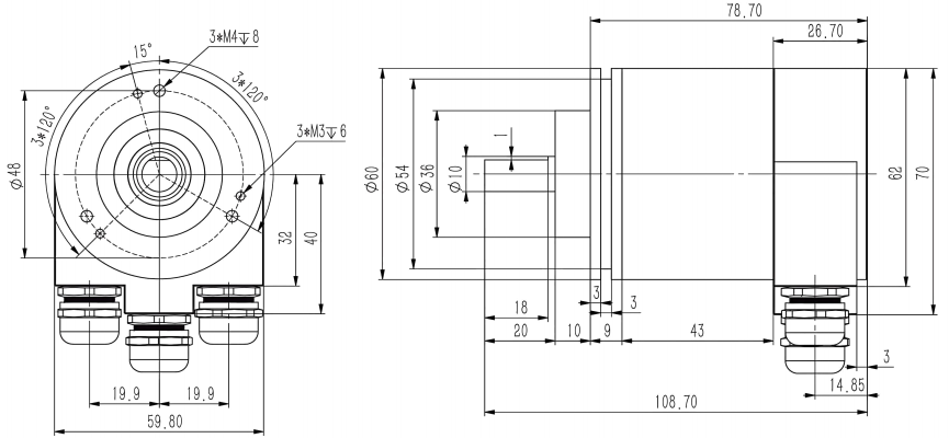
SAS/M58B
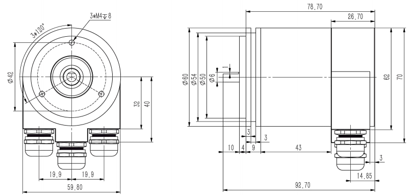
SAS/M58C

SAS/M58D

Model Selection
| SA | ① | 58 | ② | - | DP | ④ | ⑤ | - | ⑥ | - | ⑦ | ⑧ | ⑨ | - | ⑩ |
Note: Custom shaft/bore diameters, cable lengths, and interface requirements are available upon request.

SIVIDI
Email:sales@sividi.cn