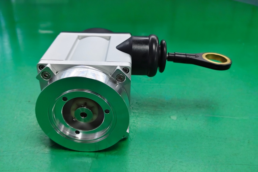
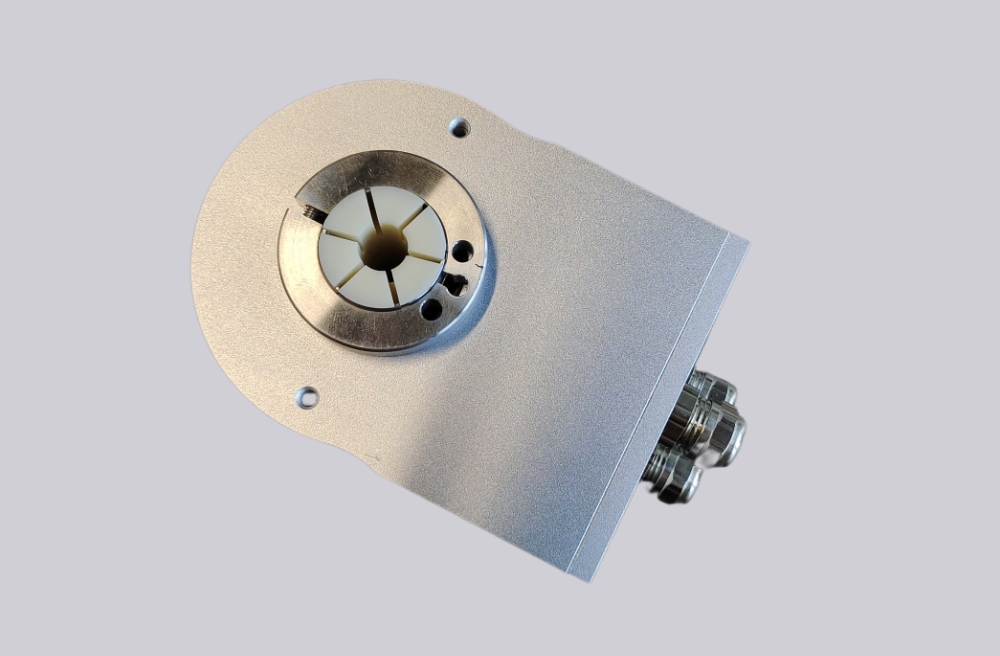
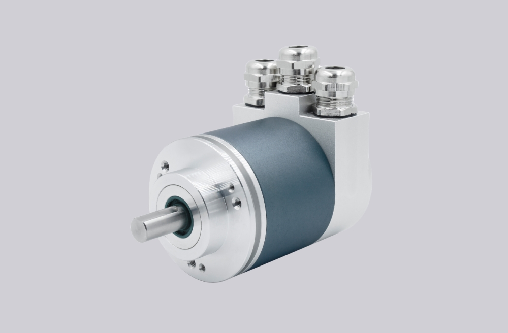
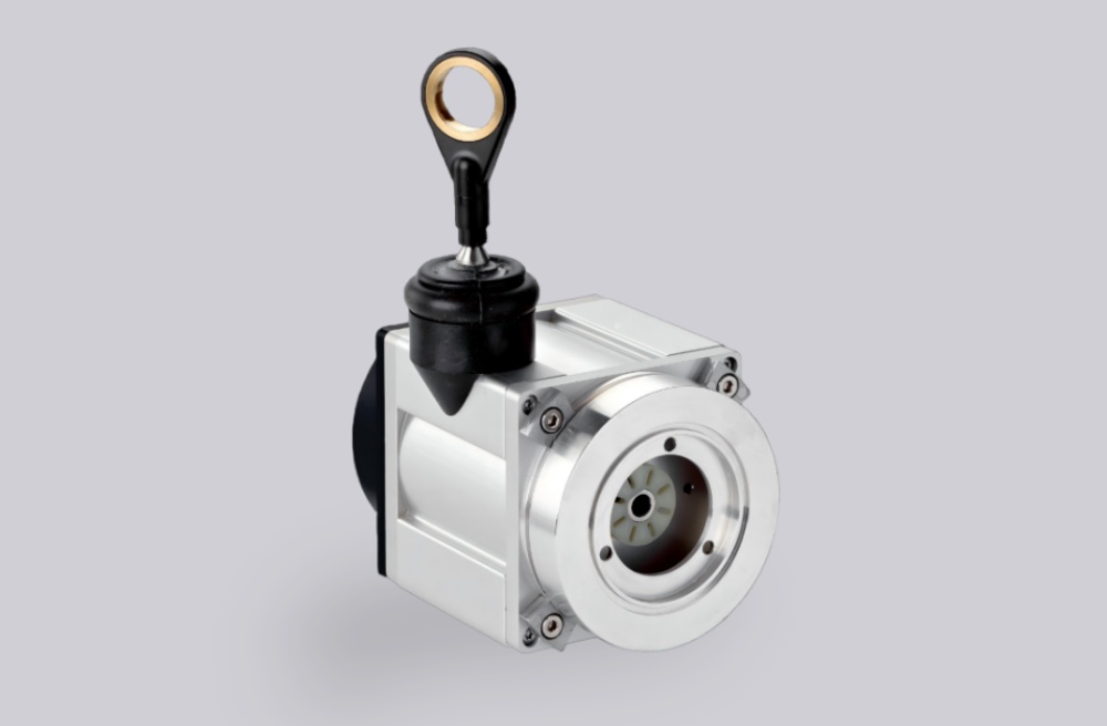
Core components are sourced through a localized supply chain to support supply continuity and stable system operation. High-precision magnetic sensing technology supports both single-turn and multi-turn absolute encoder configurations. Supports parallel push-pull outputs with selectable Gray code or binary code for integration with various industrial control systems. High shock and vibration resistance with protection ratings up to IP67 ensures reliable operation in demanding industrial environments. Built-in reverse-polarity and short-circuit protection helps protect the encoder against wiring errors.
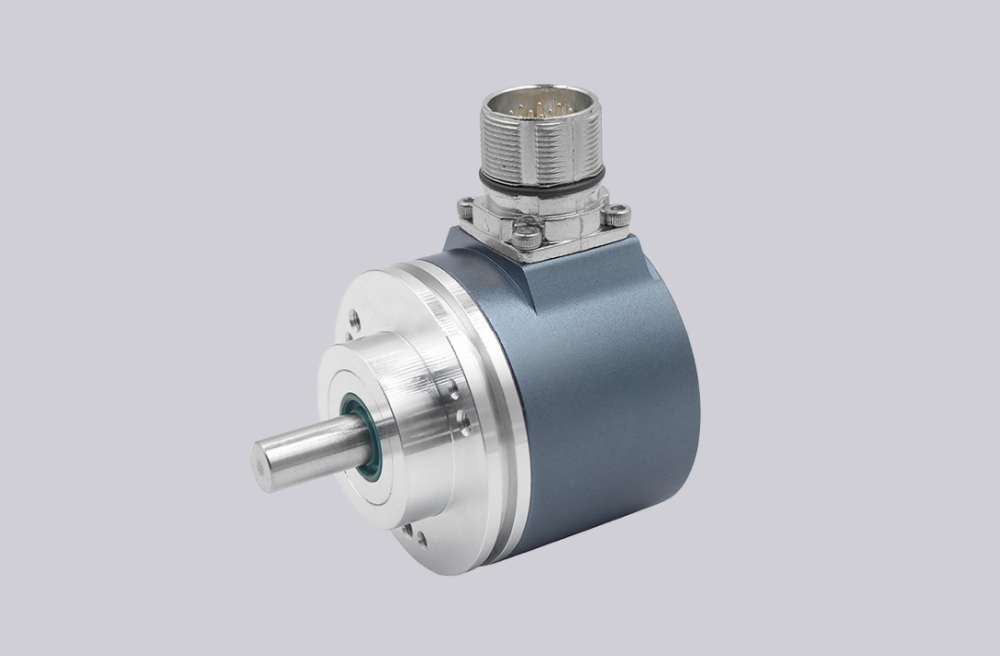
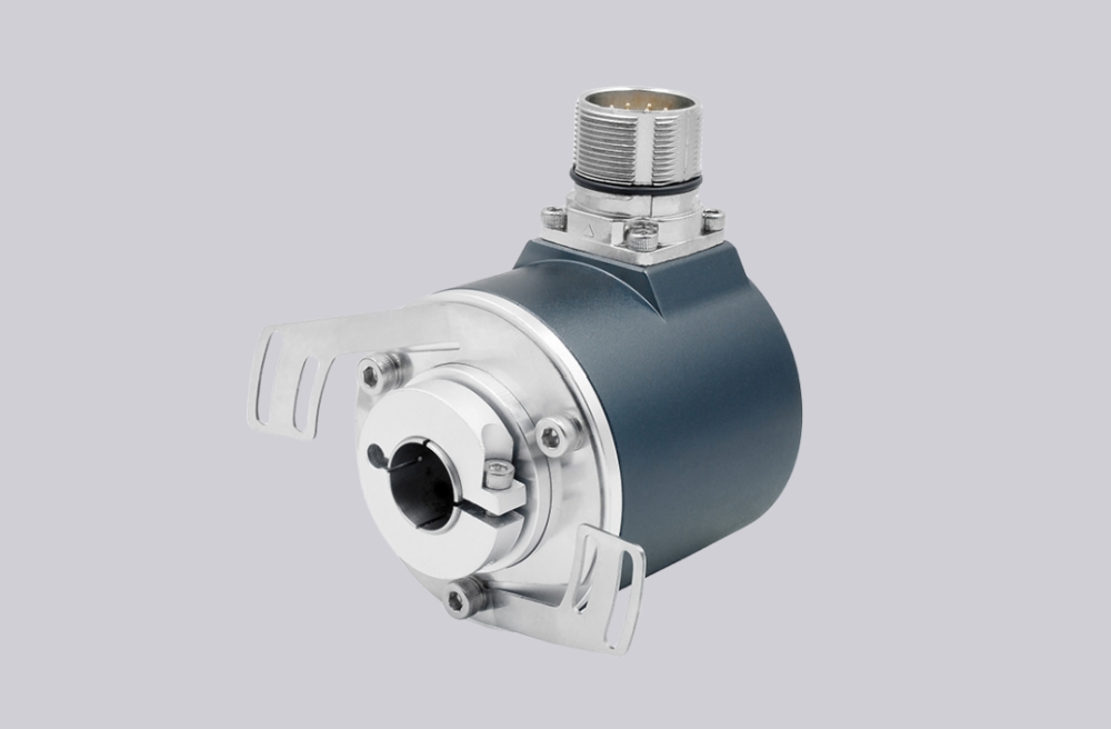
Technical Data
| Product Series | SAS/M58A | SAS/M58C |
|---|---|---|
| Shaft Type | Ø58 mm, Solid Shaft | Ø58 mm, Blind Hollow Shaft |
| Shaft Diameter | Ø6, 8, 10, 12, 14, 15 mm (Other shaft diameters available on request) | |
| Housing Material | Aluminum (Stainless steel housing optional) | |
| Output Interface | Parallel Push-pull | |
| Output Driver | Push-pull | |
| Function | Single-turn or Multi-turn | |
| Supply Voltage | 10–30 VDC | |
| Single-turn Resolution | 12 bit / 4096; 13 bit / 8192; 16 bit / 65536 | |
| Number of Revolutions | 1 revolution (single-turn); 4096 revolutions / 12 bit; up to 16384 revolutions / 14 bit | |
| Power Consumption | ≤1.5 W | |
| Control Functions | Counting direction, zero setting, latch | |
| Output Code | Gray code or binary code | |
| Reverse Polarity Protection | Yes | |
| Short-circuit Protection | Yes | |
| Surge and ESD Protection | Yes | |
| Operating Speed | 3000 rpm | |
| Shaft Load | Radial: 200 N; Axial: 100 N | |
| Degree of Protection | IP65 or IP67 | |
| Starting Torque | <0.01 Nm | |
| Operating Temperature | -40°C to +85°C | |
| Storage Temperature | -45°C to +100°C | |
| Shock Resistance | 1000 m/s², 6 ms (100 g) | |
| Vibration Resistance | 20 g | |
| Electrical Connection | 20 × 0.13 mm², 20-core shielded cable; 34 × 0.13 mm², 34-core shielded cable | |
| Connection Direction | Radial or axial | |
Terminal Assignment
| Single-turn Encoder | |||
|---|---|---|---|
| Core Colour | Binary Code | Gray Code | Description |
| Brown | Vcc | Vcc | Power Supply |
| White | 0V | 0V | |
| Black | P-set | P-set | Function Lines |
| Blue | DIR | DIR | |
| Gray | LATCH | LATCH | |
| Pink | 20 | G0 | Data Lines |
| Violet | 21 | G1 | |
| Red | 22 | G2 | |
| Orange | 23 | G3 | |
| Light Blue | 24 | G4 | |
| Light Green | 25 | G5 | |
| White/Blue | 26 | G6 | |
| White/Green | 27 | G7 | |
| White/Yellow | 28 | G8 | |
| White/Orange | 29 | G9 | |
| White/Brown | 210 | G10 | |
| White/Red | 211 | G11 | |
| White/Black | 212 | G12 | |
| White/Violet | 213 | G13 | |
| White/Gray | 214 | G14 | |
| Yellow/Blue | 215 | G15 | |
| Multi-turn Encoder | |||
|---|---|---|---|
| Core Colour | Binary Code | Gray Code | Description |
| Brown | Vcc | Vcc | Power Supply |
| White | 0V | 0V | |
| Black | P-set | P-set | Function Lines |
| Blue | DIR | DIR | |
| Gray | LATCH | LATCH | |
| Pink | 20 | G0 | Data Lines |
| Violet | 21 | G1 | |
| Red | 22 | G2 | |
| Orange | 23 | G3 | |
| Light Blue | 24 | G4 | |
| Light Green | 25 | G5 | |
| White/Blue | 26 | G6 | |
| White/Green | 27 | G7 | |
| White/Yellow | 28 | G8 | |
| White/Orange | 29 | G9 | |
| White/Brown | 210 | G10 | |
| White/Red | 211 | G11 | |
| White/Black | 212 | G12 | |
| White/Violet | 213 | G13 | |
| White/Gray | 214 | G14 | |
| Yellow/Blue | 215 | G15 | |
| Yellow/Gray | 216 | G16 | |
| Yellow/Orange | 217 | G17 | |
| Yellow/Red | 218 | G18 | |
| Yellow/Violet | 219 | G19 | |
| Pink/Black | 220 | G20 | |
| Pink/Yellow | 221 | G21 | |
| Pink/Orange | 222 | G22 | |
| Pink/Green | 223 | G23 | |
| Pink/Brown | 224 | G24 | |
| Yellow/Black | 225 | G25 | |
| Yellow/Brown | 226 | G26 | |
| Yellow | 227 | G27 | |
1) P-set External Preset Input: Single-turn zero setting: when connected to VCC, the current position is set as the zero position for the entire output range.
(This is the factory default setting. Single-turn midpoint preset is also available as a custom option and must be specified before ordering.)
Multi-turn midpoint positioning: when briefly connected to VCC, the current position is set as the zero position for the entire output range.
(This is the factory default setting. Multi-turn midpoint preset is also available as a custom option and must be specified before ordering.)
2) LATCH Data Latch: Connect to 0 V or leave unconnected for real-time position data output; connect to VCC to latch the current position value.
3) DIR Counting Direction Input: Connect to VCC for increasing position values with counterclockwise rotation when viewed from the shaft end; connect to 0 V for increasing position values with clockwise rotation.
4) Shield: Cable outlet.
Note: 1416 requires customization. Custom connectors are available according to customer requirements.
Mounting Dimensions
SAS/M58A

SAS/M58B

SAS/M58C

SAS/M58D

*Note: Axial cable outlet length is 42 mm; radial cable outlet length L is 53 mm.
*Aluminum housing: d = 59 mm; stainless steel housing: d = 61 mm.
*Aluminum housing: d = 59 mm; stainless steel housing: d = 61 mm.
Model Selection
| SA | ① | 58 | ② | - | ③ | ④ | ⑤ | - | ⑥ | - | ⑦ | ⑧ | ⑨ | - | ⑩ |
Note: Custom shaft/bore diameters, cable lengths, and interface requirements are available upon request.

SIVIDI
Email:sales@sividi.cn