The core components of the product are 100% localized, ensuring a stable and reliable supply chain as well as outstanding product quality.
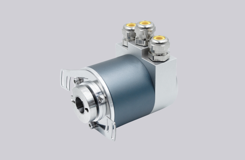
It adopts high-precision magnetic sensing technology, providing both single-turn and multi-turn absolute encoder solutions.
Supports the Profibus-DP bus, enabling high-speed and stable data communication in industrial field applications.
Single-turn resolution is available up to 16 bits, while multi-turn resolution reaches 14 bits, meeting high-precision measurement requirements.
Features excellent shock and vibration resistance, with a protection rating of up to IP66, making it suitable for harsh industrial environments.
Built-in reverse polarity and short-circuit protection effectively reduces the impact of installation errors on the encoder.
Technical Specifications (Profibus-DP Series)
| Parameter | SAS/M58A (Solid Shaft) | SAS/M58C (Hollow Shaft) |
|---|---|---|
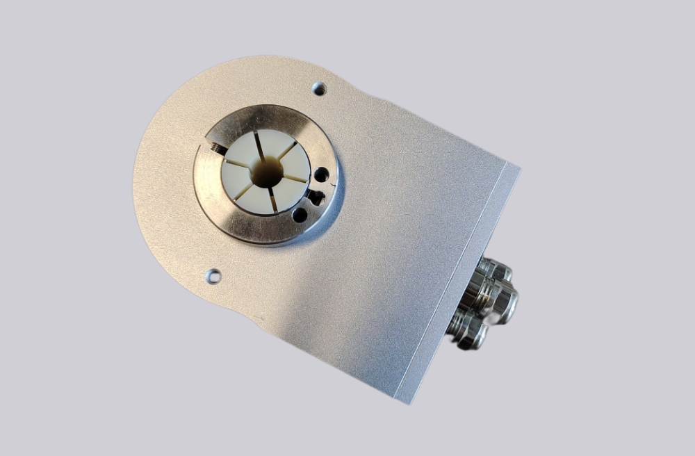
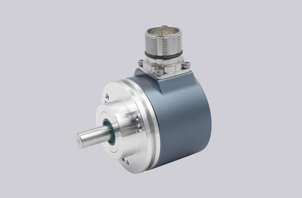
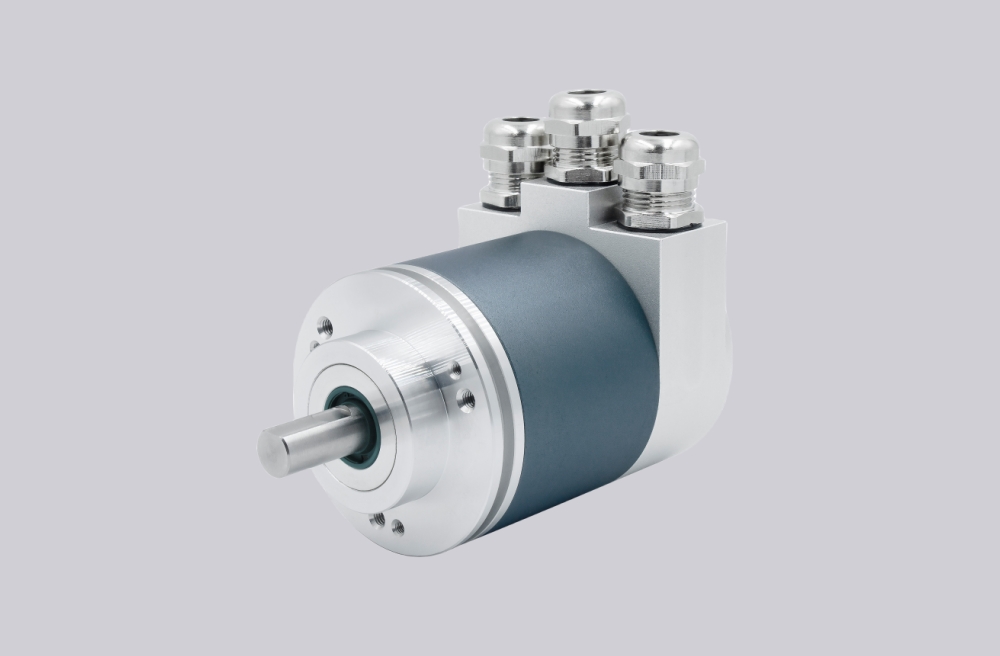
| Design | Ø 58 mm solid shaft | Ø 58 mm hollow shaft |
| Shaft Diameter | Ø 6, 8, 10, 12, 15 mm (other sizes available on request) | |
| Housing Material | Aluminum (stainless steel housing optional) | |
| Signal Output Interface | Profibus-DP bus | |
| Protocol | DPV0, DPV1 and DPV2 Class 2 (EN50170 + EN50254) | |
| Output Driver | Profibus data interface, opto-isolated | |
| Function | Single-turn or multi-turn | |
| Supply Voltage | 10 ~ 30 VDC | |
| Single-turn Resolution | Standard: 12-bit (4096), 13-bit (8192), 16-bit (65536) | |
| Number of Turns | 1 turn (single-turn); multi-turn standard 12-bit (4096 turns); optional up to 14-bit (16384 turns) | |
| Power Consumption | ≤ 1.5 W | |
| Interface Cycle Time | ≥ 1 ms | |
| Programming Functions | Resolution, speed scaling + filter, preset (zero position), counting direction, limit switches, node address, teach-in mode, diagnostic mode | |
| Transmission Rate | ≤ 12 Mbit/s | |
| Manual Functions | Address selector switch 0–99 and termination resistor DIP switch (with terminal box) | |
| Code Type | Binary code | |
| Mechanical Characteristics | Maximum speed: 6000 r/min | Shaft load: radial 200 N, axial 100 N |
| Protection Rating | IP65 or IP66 | |
| Starting Torque | < 0.05 Nm | |
| Connection Type | 3 × M12 connectors | |
| Cable Outlet | Radial side outlet, axial rear outlet | |
Wiring Definition
| Signal | Description |
|---|---|
| ⊥ | Power supply ground (PE) |
| B (Left) | Data line B (pair 1), bus input |
| A (Left) | Data line A (pair 1), bus input |
| (-) | 0 V |
| (+) | 10 V … 30 V |
| B (Right) | Data line B (pair 2), bus output |
| A (Right) | Data line A (pair 2), bus output |
| (-) | 0 V |
| (+) | 10 V … 30 V |
| Note | The power supply needs to be connected only once (to either terminal set); when the termination resistor is enabled, BUS OUT is disconnected. |
LED Indicators
| Red LED | Green LED | Status information / Possible causes |
|---|---|---|
| Off | Off | No power supply |
| On | On | The rotary encoder is ready for operation, but has not yet received any voltage-based configuration data; possible causes include, for example, incorrect address setting or incorrect bus connection. |
| On | Blinking | Parameter assignment or configuration error. The length of the received configuration or parameter assignment data is not plausible or the data is inconsistent; possible causes include, for example, an excessively high total resolution setting. |
| Blinking | On | The rotary encoder is ready for operation, but is not being accessed by the master (e.g. this condition may occur due to an incorrect address). |
| On | Off | The rotary encoder has not received any data within a certain period (approx. 40 seconds); the data line may be interrupted. |
| Off | On | Data exchange is operating in normal mode |
| Off | Blinking | Data exchange is operating in commissioning mode |
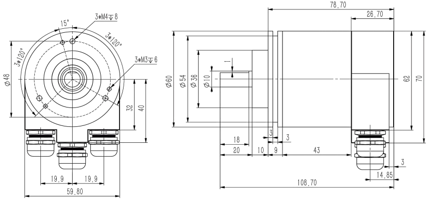
Mounting Dimensions
SAS/M58A
SAS/M58B
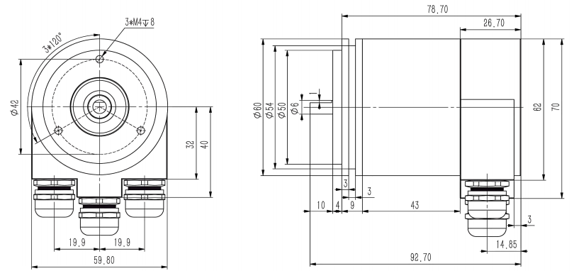
SAS/M58C

SAS/M58D

Real-Time Model Configuration
| SA | ① | 58 | ② | - | DP | ④ | ⑤ | - | ⑥ | - | ⑦ | ⑧ | ⑨ | - | ⑩ |
Note: For special shaft diameters, bore sizes, or cable length requirements,
please contact us for customization.
SIVIDI
Email:sividi360@outlook.com